Crank and block part 2

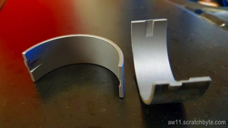
I got some comments recently from bot, who suspected that the middle main cap deforming while ARP nuts were tightened could be the reason behind my seized crank.

The possibility of twisted or tweaked middle main cap didnt cross my mind. I had already gotten my block back from machine shop, when bot commented this thing, but I didnt have spare time to actually look my block until now.

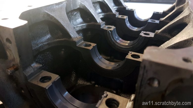
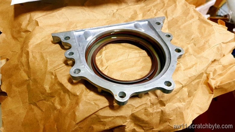
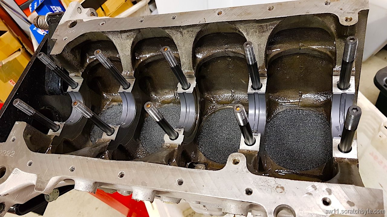
I spent two hours carefully taking everything apart and examining the parts (once again). Block still had some cutting oil + metal particle residue from the honing and it probably was also mixed with that ARP moly stuff that was used on the threads. It took some time to get everything clean.

Below: I made a set of cylinder plugs from foam plastic to help with cleaning and installing parts.

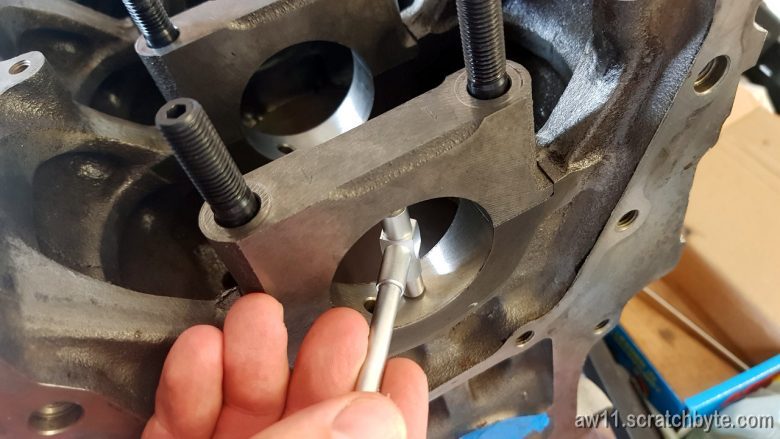
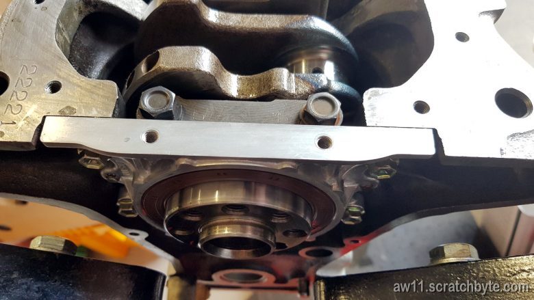
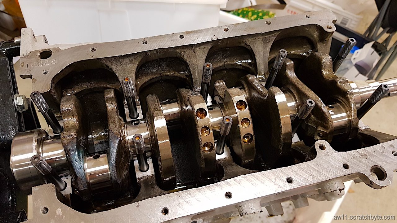
Putting everything back together went well. Bearings and ARP studs went in smoothly and so did the crank (after cleaning it millionth time). When I got to the thrust bearings I eyeballed them with suspicion but they didnt reveal anything to me. Lower ones slid in easily and the upper ones went in with the main cap.

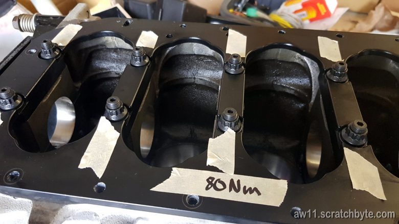
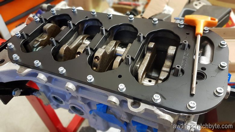
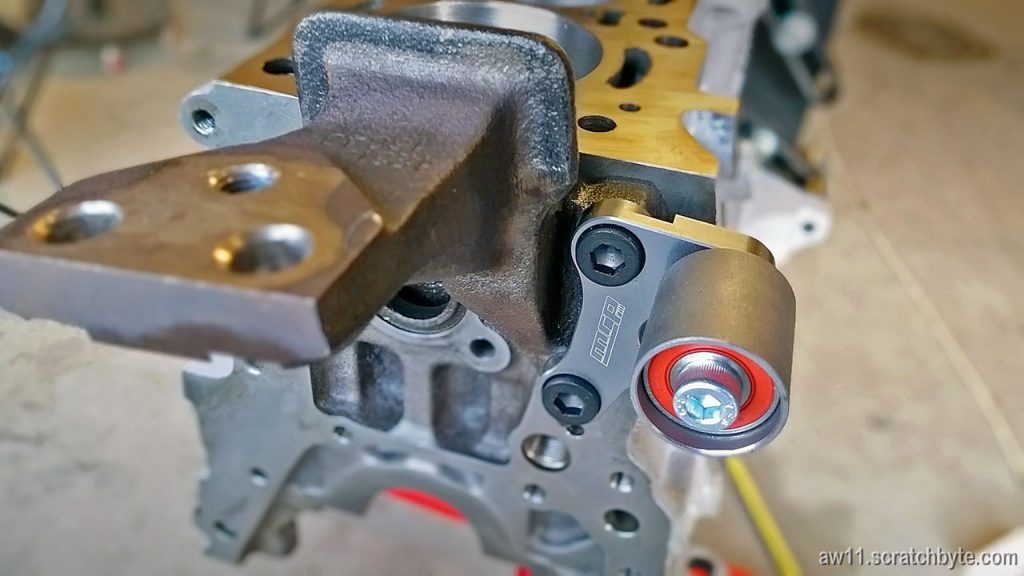
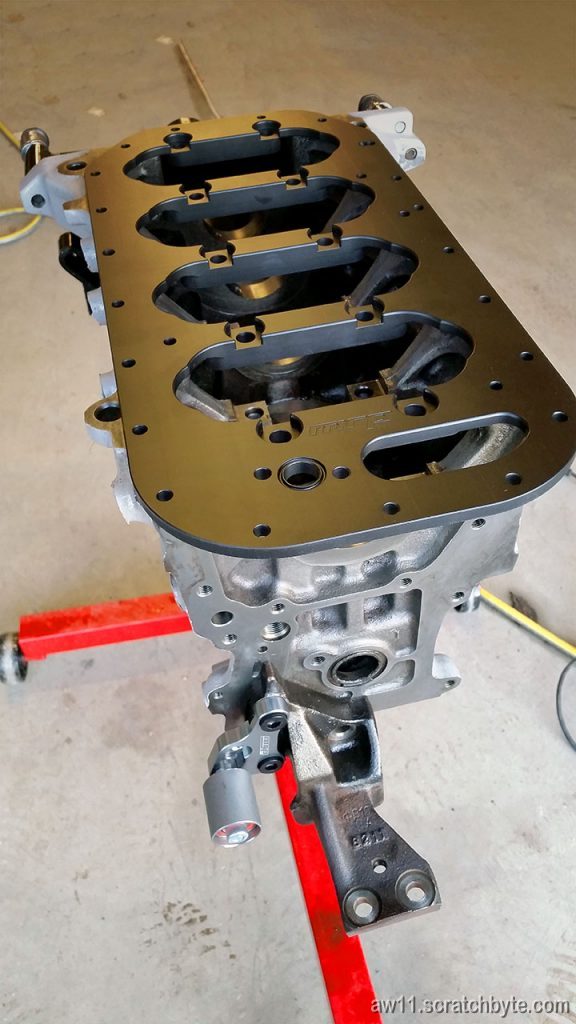
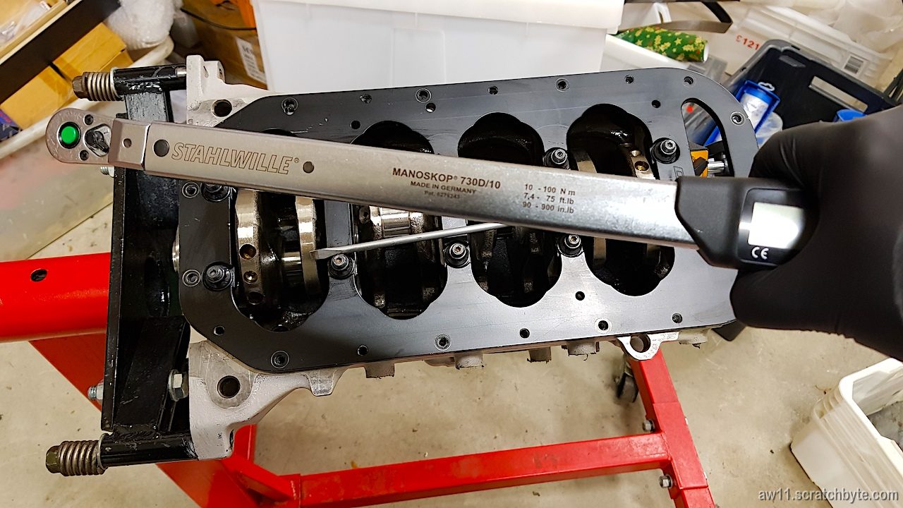
Last bits were the MRP girdle and ARP washers and nuts. I tightened the nuts in four steps starting from 20Nm and ending to 80Nm, stopping in between to rotate the crank and see if there were any problems. The crank rotated freely every time.

Below is my torque wrench. I bought this one just for this project to get the critical parts correctly torqued.

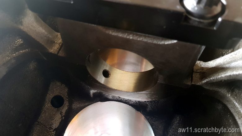
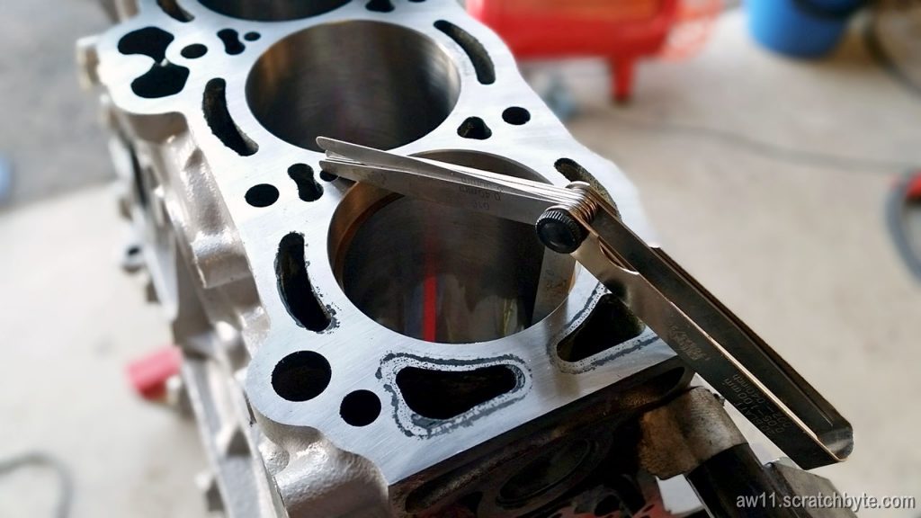
It started to seem that the honing did help and the middle cap wasnt causing any trouble. I grabbed the crank from the both ends and tried to shake it, but it felt like there wasnt any play. I went to get Widrics almost unused dial indicator and set it up.

Below: zeroed

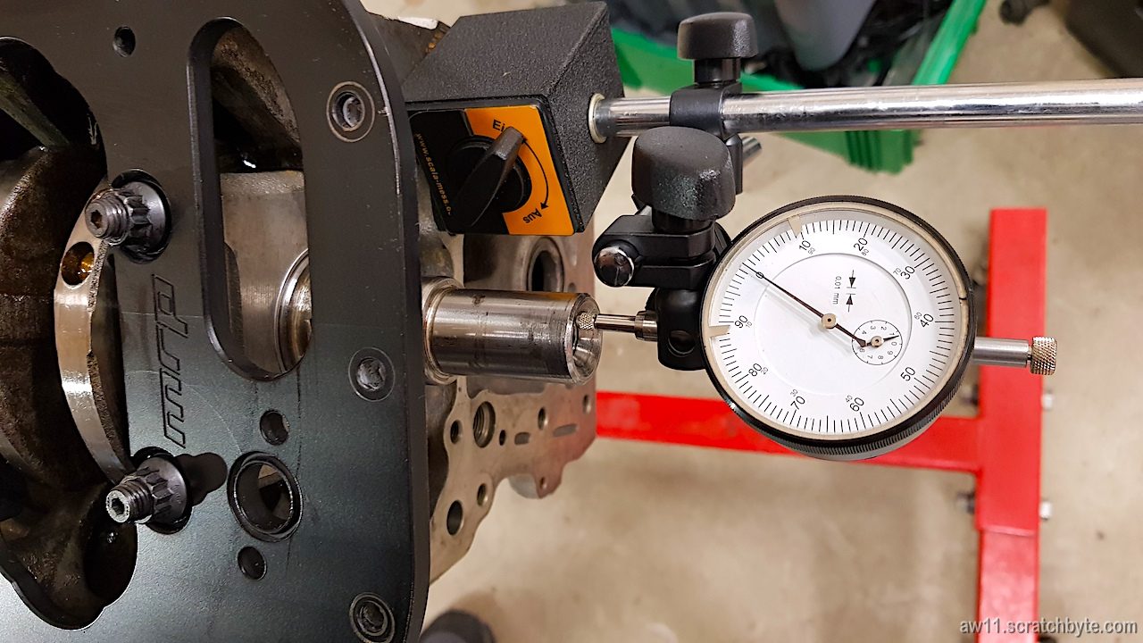
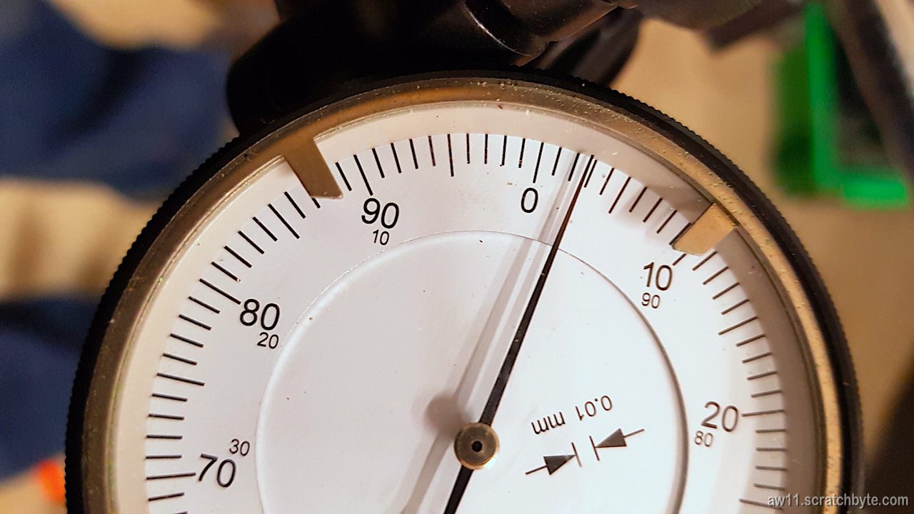
Then I poked the crank with screwdriver like the Toyota manual says.

Result: seems that my crankshaft end play is 0.03mm. Toyota manual says that the minimum acceptable is 0.02mm 😀

Some thoughts:

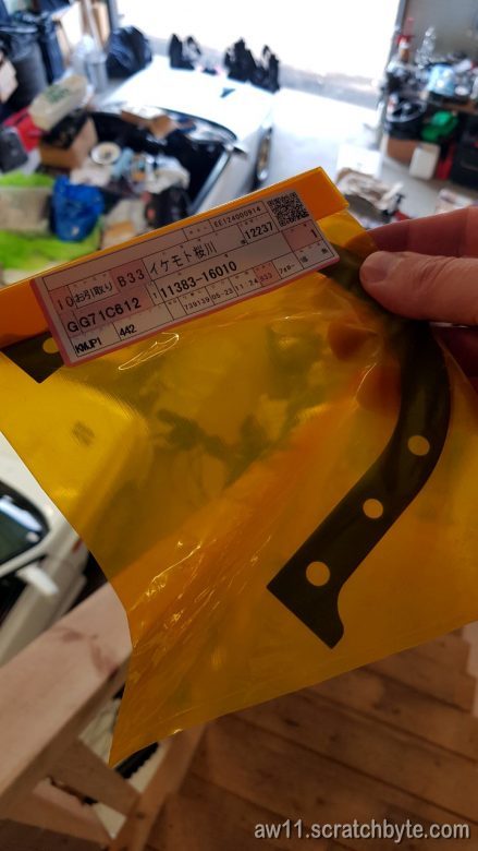
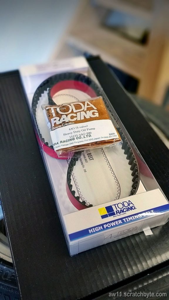
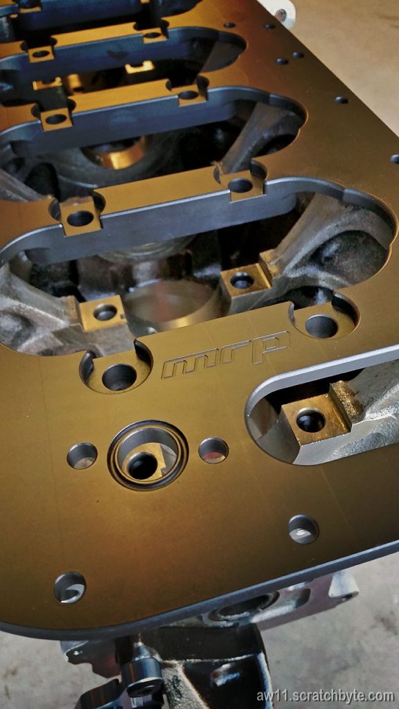
I’ve introduced plenty of new parts to my engine block. I have new main bearings and new thrust bearings, both with extra moly coating on them. Also, a set of longer ARP studs (with washers and nuts) for the girdle and the girdle itself.

Every new part creates a huge number of unknowns and it is absolutely important to check that everything is where they should be. Mr. Manon probably disagrees with me, but even the girdle could have been the source for my problems, although it got complemented by the machinist doing the honing 😀

Just by fitting all the parts together I found out that the middle main cap was not the problem. I’m not entirely happy of this method, but it has to do now. I dont have the resources and possibilities of McLaren to build engines 😀

Edit: My preferred method for the problem would have been different. I prefer to measure things until I have numbers, results and hard evidence. Except putting things back together was more practical and efficient method… 😀

I didnt measure the bearings yet, so next time I’ll be messing with plastigage.

and _o/ to bot!

The tide has turned part 2

After the crank got stuck, I disassembled everything:

Bearings looked still good and the molybdenium coating was not affected.

Little bit of measuring – picture below is staged 😀

While having the girdle plate on and everything tightened, the crank bore shrunk to 51,98mm. Didnt expect to see chunks of steel deform so much that the crank line bore would be out of spec (it should be 52mm)

Well, this meant a trip to machinist. Assembled everything back and made sure that the block and girdle were ready for the crank line honing.

Before honing:

…and after honing:

Plenty of cleaning ahead, but the machinist said that the inside diameter  is now 52.03mm.

The crank was also checked for straightness. Weirdly enough, it was 0.03mm out of straight, but now only 0.02mm. For some reason being stored for a year made it little bit more straight 😀


The tide has turned part 1

I reached the turnaround point! Now I’m putting things back together and going towards working engine 🙂

There were problems, though.

New ACL bearings coated in solid molybdenium for extra slippery and first start safety.

Crank test fit. Stock bolts and oil pump.

Rear main seal bracket and the seal itself. Below, the gasket for the bracket.

Seal in place. Left side you can see the 22221 number which indicates the crank line bore sizes.

Glueing the crank girdle to place with Permatex Supra Grey. Main bolts swapped to ARP studs and nuts.

This is where the problems started.

I left the gasket goop to dry for an hour and came back to tighten the main stud nuts. I quickly glanced the ARP installation procedure and thought that it is funny how ARP recommends the tightening torque to be the same as Toyota stock, which is 60Nm. Tightened everything in three steps and then I tried to rotate the crank. It wasnt turning as freely as I hoped.

I checked everything. Removed nuts, removed studs and checked everything possible. Tried tightening again to 60Nm but no dice. There still was a point where the crank felt like it was stuck. Then I read the ARP installation document again and to my horror ARP recommendation wasnt 60Nm, instead it was 60ft/lbs, which is around 80Nm.

The crank seized totally. It only turned a bit when I helped it with the biggest rubber mallet I could find in our garage. Shit shit shit fuuuuuck.

Piston rings + crank girdle

Checking pistons and rings:

Gap on fourth cylinder is 0.35mm.

Pistons seem to fit into block. That is a good thing.

A package from Manon Racing Products arrived, containing Toda timing belt and oil pump gears, N2 style additional timing belt tensioner (or guide) and a crank girdle.

Timing belt tensioner. Fitment is very good.

And the crank girdle. A serious piece of hardware. I needed only some stiffening but now the engine will be bombproof.

Veeery nice 🙂

Turbo project – something to show

Mr. Manon from Manon Racing Products, NZ made me a turbo manifold 🙂

20140925_155918

I havent yet bought the actual turbo, but I have a manifold at least! It is custom made to fit a BorgWarner EFR6255 or 6258 turbine into AW11.

Here are some measurements of the engine compartment I took for Mr. Manon to see if it would fit. The engine in the picture is a naturally aspirated one and the trunk side is not very accurate. Also, seems that at least my engine sits somewhat tilted towards forward for unknown reasons.

Measured distances should be accurate to 10mm.

engine-4agze

Click the picture for a bigger, clearer one.