About one day worth of dyno time to get the legal issues handled. The dude mooning the camera is there to keep an eye on the fuel pressure gauge.
After first tuning session
Some things and problems:
Clutch. Most likely at some time in the past I’ve tried to adjust the master cylinder rod behind the pedal and messed everything. The clutch hydraulics work very well now I’ve rebuilt the pipe from master cylinder to slave, but the disengagement point is at the very top.
Oil pan. It leaks. I should have RTV’d it against the crank girdle, but decided to use a gasket. The gasket doesnt seal – even if I tighten the oil pan screws to absolute maximum.
Intercooler heat exchanger needs to be bigger and somewhere else + the car needs a oil cooler.
Oil catch can – the car needs one. I routed the breather hose from the engine to the top of the gearbox which lead me to wonder if I had a broken rear seal. Widric, who first found oil dripping on the floor initially thought that the oil was coming from the gearbox.
Everything else worked surprisingly well – even the fuel tank cap which I had to “borrow” from friends Toyota Dyna. I’ve misplaced the original cap.
Dyno days part one
Dyno days – tuning the car to meet legal restrictions. After this is done, I’ll ask the tuning company to find out how much the car makes now
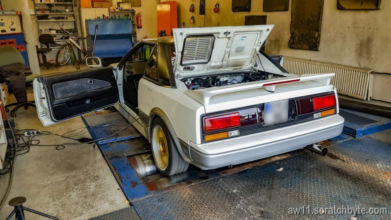
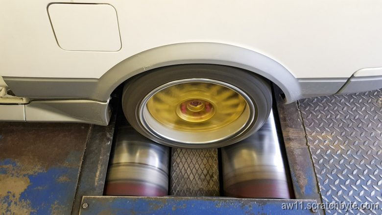
I probably sprayed a full can of anti slip spray on the rollers
Very healthy orange glow from the exhaust manifold!
Video coming soon
Grounding and reverse light wiring
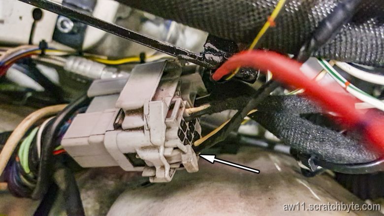
The arrow points the terminal where reverse lights are wired. A red/black wire goes from this terminal to the reverse light switch on top of the gearbox.
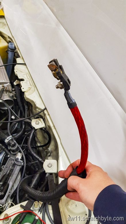
A thick extension for the battery positive. Also, makes things easier when there is just single wire going to the battery terminal
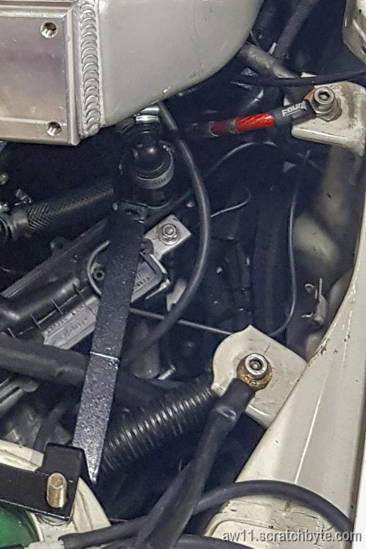
Also, I decided to use the stock intercooler mounting points as new body grounding. The picture is missing a wire that goes between the two mounting points.
The red wire on the the second mounting point is also for grounding. I taped it black bit later to keep red wires positive and black wires as ground.
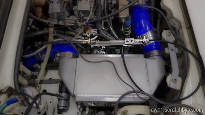
Extending the stock throttle cable
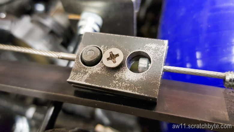
Just a easy extension for the cable
I later replaced the screw in the middle with allen bolt and a locking nut.
Replacement for the broken boost pressure recirculation valve
Broken one removed
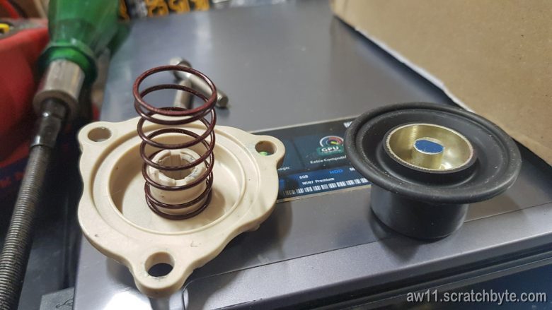
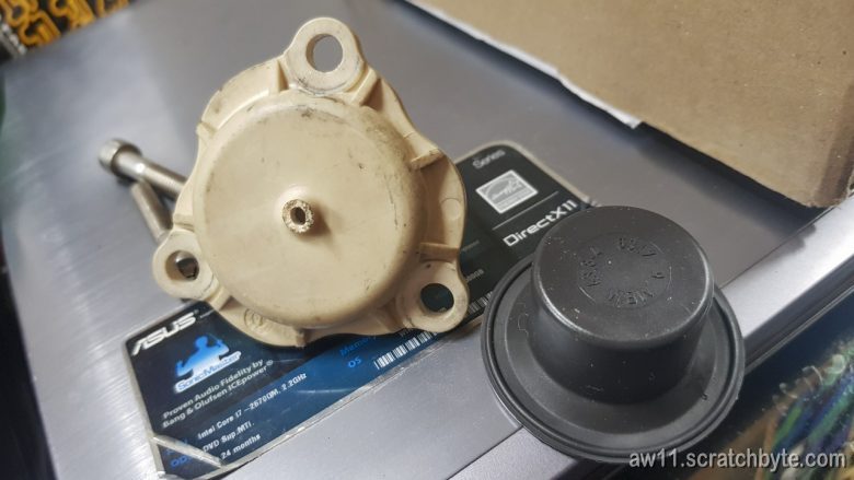
Here is the replacement: Go Fast Bits DVX T9654. Replacement was easy and the full metal body and pressure fitting felt sturdy.
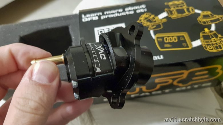
I was explaining what had happened to a friend of mine, who misheard the name and thought I said “Go Fast Bitch” – he said to me bit later that this is the most ballsy company name he has heard in a while.
Stock tacho with aftermarket ECU
Normally the Toyota tacho doesn’t work with aftermarket ecu. The Toyota tacho needs a high voltage pulses from coil to work. I didn’t want to build a voltage booster from modified relay or anything like that, which meant I had to look into the tacho electronics.
I googled a bit, read some forum posts about toyota tachos and then decided to try something. Guessing is sometimes good – I guessed the first resistor after the signal terminal has something to do with this thing.
I bypassed the first resistor completely and the tacho came into life. Simple and nice.
Note: following resistor values worked for me – check yours if you’re doing something similar
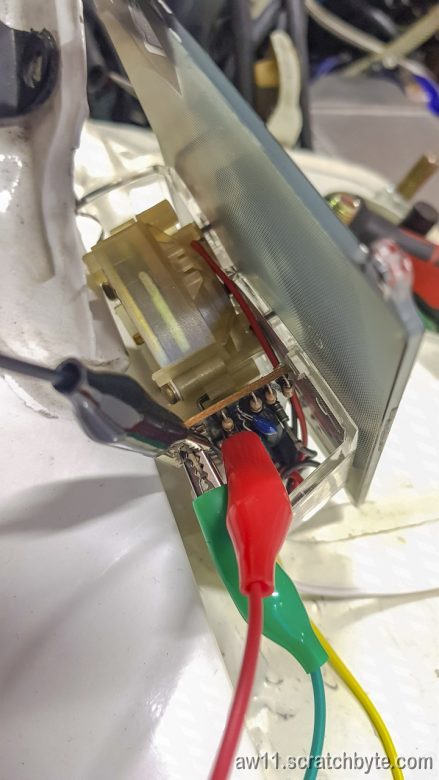
I didn’t want to tear my dash at this point so I tested with the 10k tacho
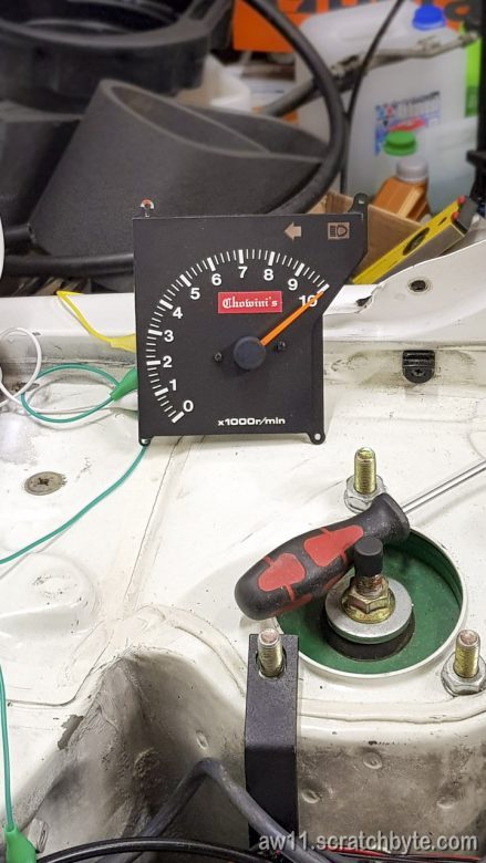
I measured the first resistor and it was in the 30kohm ballpark. I thought there should be some resistance in the signal path so I had to find out what the resistance needed to be so it would work with aftermarket ECU signal.
The easiest way was to solder a resistor parallel to the original to lower the total resistance.
I bought a pack of random resistors and a linear potentiometer to find out what I need.
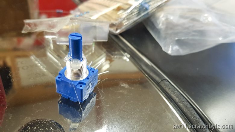
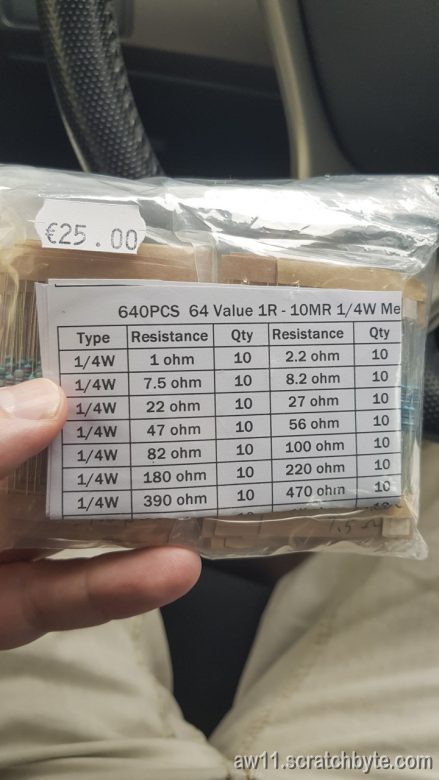
The resistance where the Toyota tacho started to work was 15kohm, which meant I needed a similar 30kohm resistor parallel to the original
Tore out the stock tacho
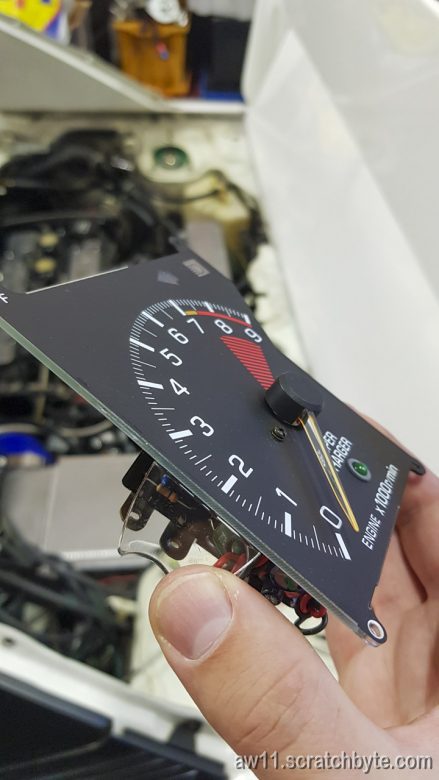

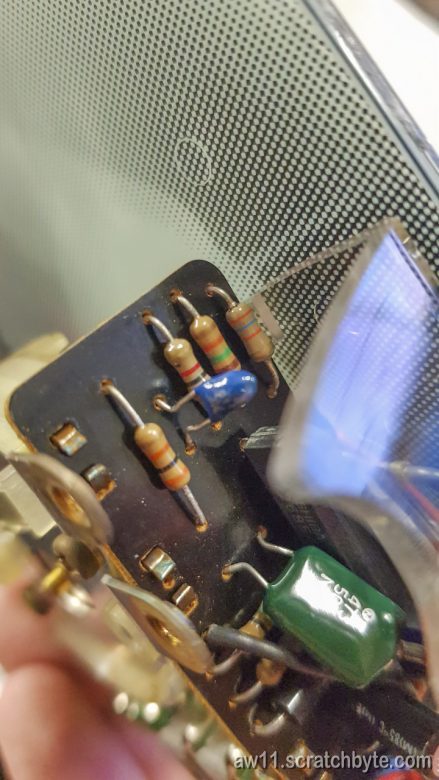
…and soldered a second resistor parallel using the stock resistor leads

It worked. Stock tacho works now.
Building a coil pack support with some lipstick for pigs
Built this using 5mm aluminium.
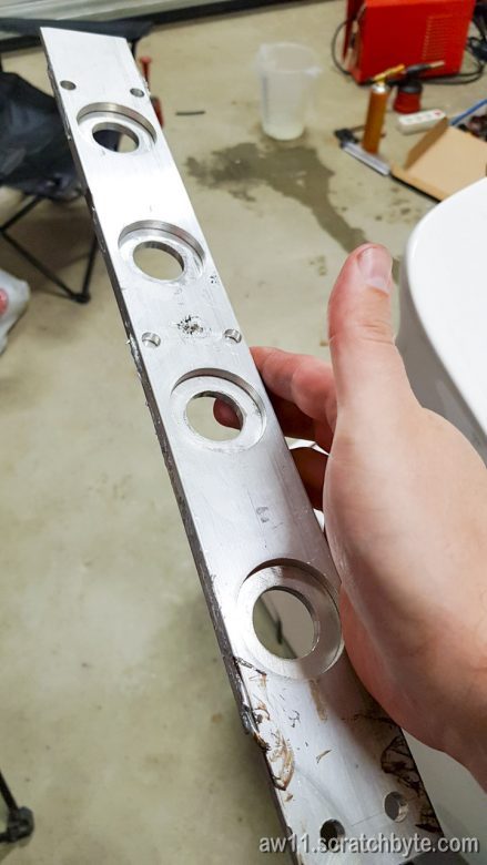
Just checking the holes are somewhat close where they should be
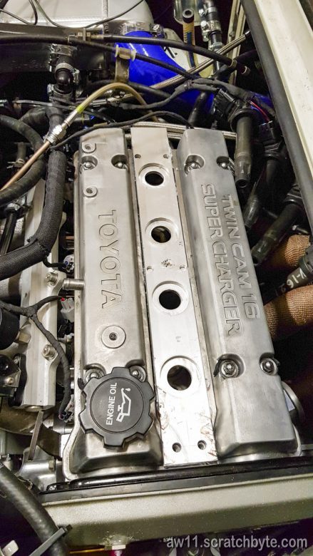
The coilpacks do fit – a positive thing 😀
Coilpacks are from V6 Lexus RX (or Toyota Harrier) part number 90919-02246 with the normal toyota coil pack pinout.
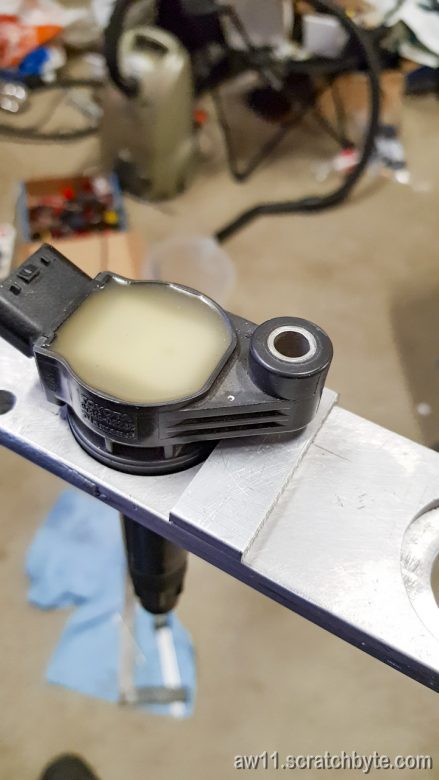
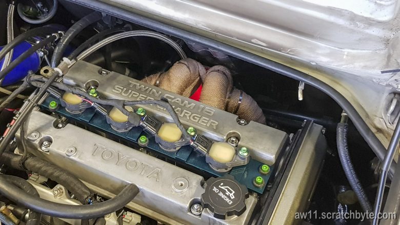
Decided to add some performance adding bits. The green bolts are anodised titanium. Added at least 10hp each.
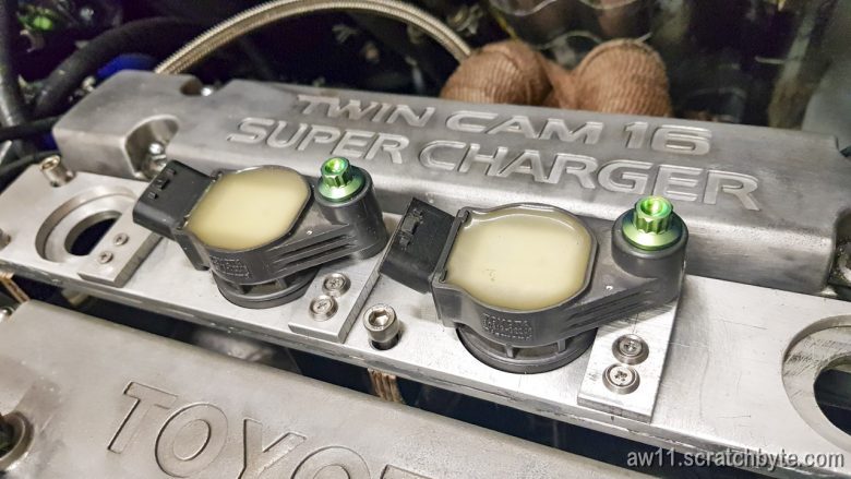
I’ll probably do a upgraded version of the support bit later, but for now this has to do. Below the allen head bolts are green anodised aluminum just because I couldn’t find short titanium ones.
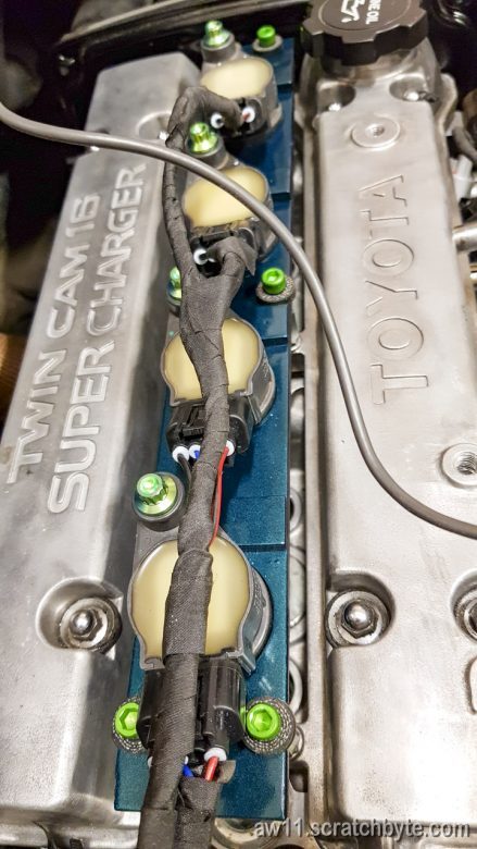
All the green bits added at least 75hp more power
Learning to weld
I had to teach myself to weld so I could build brackets for new parts
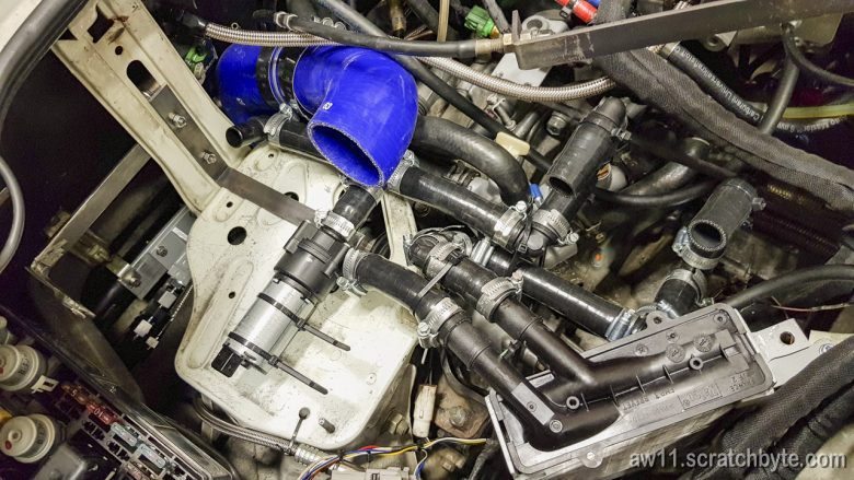
Below is my first test for IC water pump and heat exchanger setup. Found out later that small heat exchanger behind gearbox doesn’t do shit.
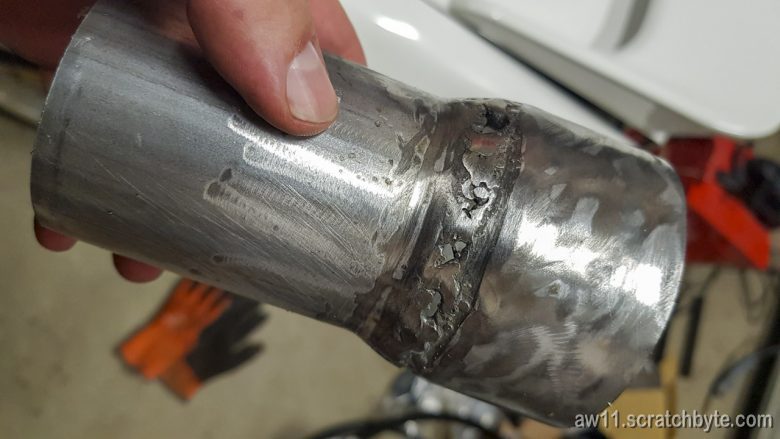
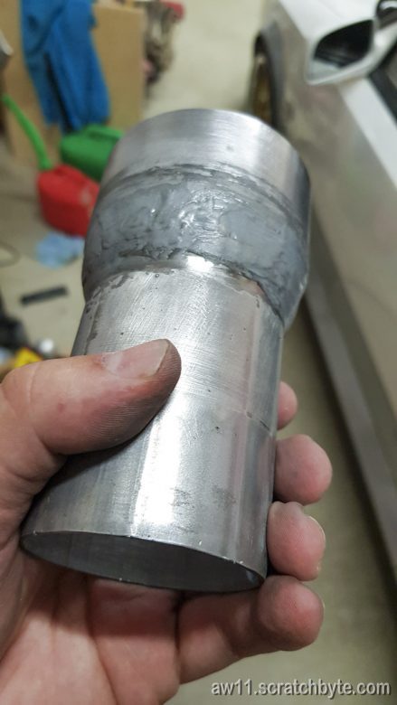
This sad excuse of welding is a intake air filter adapter. Bought some exhaust parts from local store and welded them together.
Then epoxied all the holes with metal epoxy.
Installing turbo hoses
While trying to install all the required hoses for the turbo, I encountered a design problem.
The turbo solenoid below was somewhat easy

But when I tried to install the turbo end for the recirc system hose, I broke the nipple off.
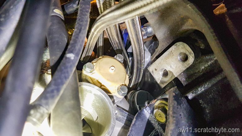
Why the hell is it made of brittle plastic?

