That JIS/BSP thread at the end of the fuel tank hardline is officially a difficult one to come by. Seems it is going to be easier to cut it off together with the flare and replace it with compression fitting.
The fuel line outer diameter is really close to 8mm and every place in the internet is full of 8mm to AN6 adapters. Im gonna go for Fragola 892005BL, because it is rated for 10 Bar (150psi) just to be sure.
Critical things missing – copied from earlier post
Cam followers (1SZ-FE solids or Supertech CF-28/3.65)
Wiring loom (the stock wiring of the maxxecu is very long – not sure if anything serious needs to be done)
Oil filter relocation hoses and misc bits
Oil filter relocation other end (I might reuse the old mocal I have)
TPS sensor (Possibly toyota stock)
TPS sensor connector (Whatever toyota stock uses)
Fuel system hoses, ethanol compatible (One or two missing)
8mm (5/16″) fuel hard line to AN6 fitting
Turbo oil line and drain
Turbo coolant line and drain
Non-critical things missing
New plugs (maybe, I got iridiums both on my current and spare engine)
Clutch plate (maybe, no idea about the current condition)
Cam gears (maybe later and maybe toda. HKS Camshafts work with stock ones)
Rear motor mount + damping?
Shift lever bushing? (what was this?)
Titanium axle bolts 🙂
Silicone coolant hose kit
Engine bay coolant bleeder screw
Flex fuel sensor (when the time comes)
Hydraulic throwout bearing (MRP)
Stuff that needs to be done
Cleaning block (in progress)
Done list
Fuel system bits and misc (plenty of AN6 adapters and ORBs)
Oil filter relocation take off plate (Canton Racing CM 22-595)
Intercooler (custom A2W from Plazmaman)
Adapter for Pivot fuel pressure dash gauge, decided to go for M8x1 to 1/8″ NPT adapter, this replaces the 5th injector banjo hose on fuel rail. Perfect!
Fuel pressure gauge (Radium)
Radium fuel pressure regulator (E85 compatible)
Radium fuel pressure damper (E85 compatible)
CAN Bus wires for the ecu
Intake + throttle body
Plan A – custom intake is being made (Waiting)
Plan B – Techno Toy Tuning adapter ordered for smallport intake (Done!)
Trigger wheel
Plan A – ordered from Techno Toy Tuning (Done!)
Plan B – next door Toyota guy makes one (Waiting still but yeah)
New pulleys (ordered from TTT, arrived, done!)
Coatings for pistons, turbo and exhaust manifold (Done!)
Cleaning cylinder head (Done! Found out that Aluminum boat cleaner works well (Oxalic acid))
Injectors + connectors (Done! EV14 714cc with ethanol compability)
Ethanol compatible fuel pump (Done! AEM)
Cam covers (Done! But doing then better this time)
Crank bearings (Done! Friction reducing coating)
Conrod bearings (Done! Friction reducing coating)
Exhaust and downpipe (Done!)
Head gasket (Done, Cometic)
New pistons (Done, Matrix Garage/Arias/Traum pistons)
Gear shifter that small bearing that is at the side of the shifter (Done! Matrix Garage)
Gear shifter bearings (Done! Matrix Garage)
Shift base bushings (Done! Matrix Garage)
2-component silver paint for the epoxy painted parts (Done, tried new type of 2K paint)
Fuel pressure regulator (Done, found the missing parts 😀 – actually got a new one from Radium)
Crank wheel/harmonic balancer (Done, I found a aluminium one from my stash)
Rear tie rods (Done, Matrix Garage + installed)
CLT sensor (Done! Bought a stock Toyota one. Thread is M12 x 1.5 – maxxecu suggest using a bosch CLT)
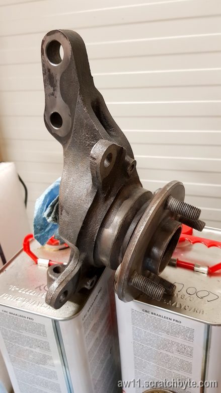
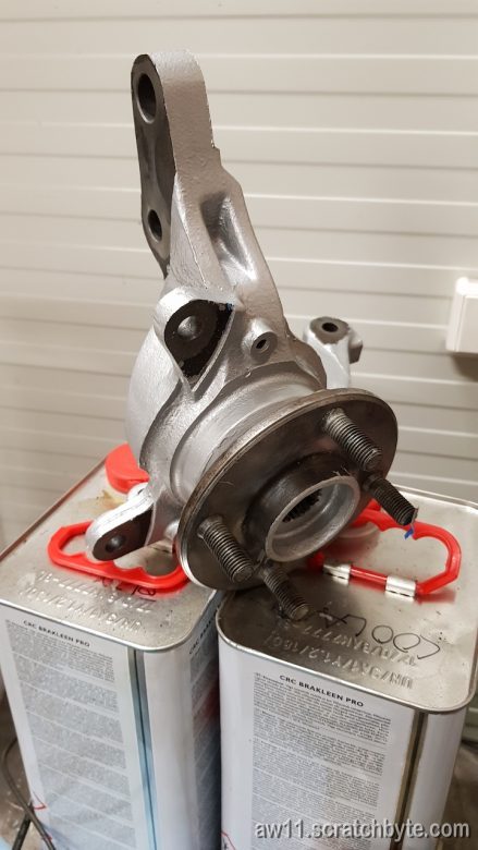
I repainted the rear knuckles while Mr. Reynolds swapped me the bearings.
Coated in epoxy and silver chemical resistant paint.
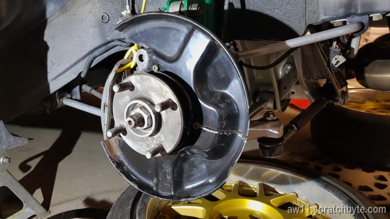
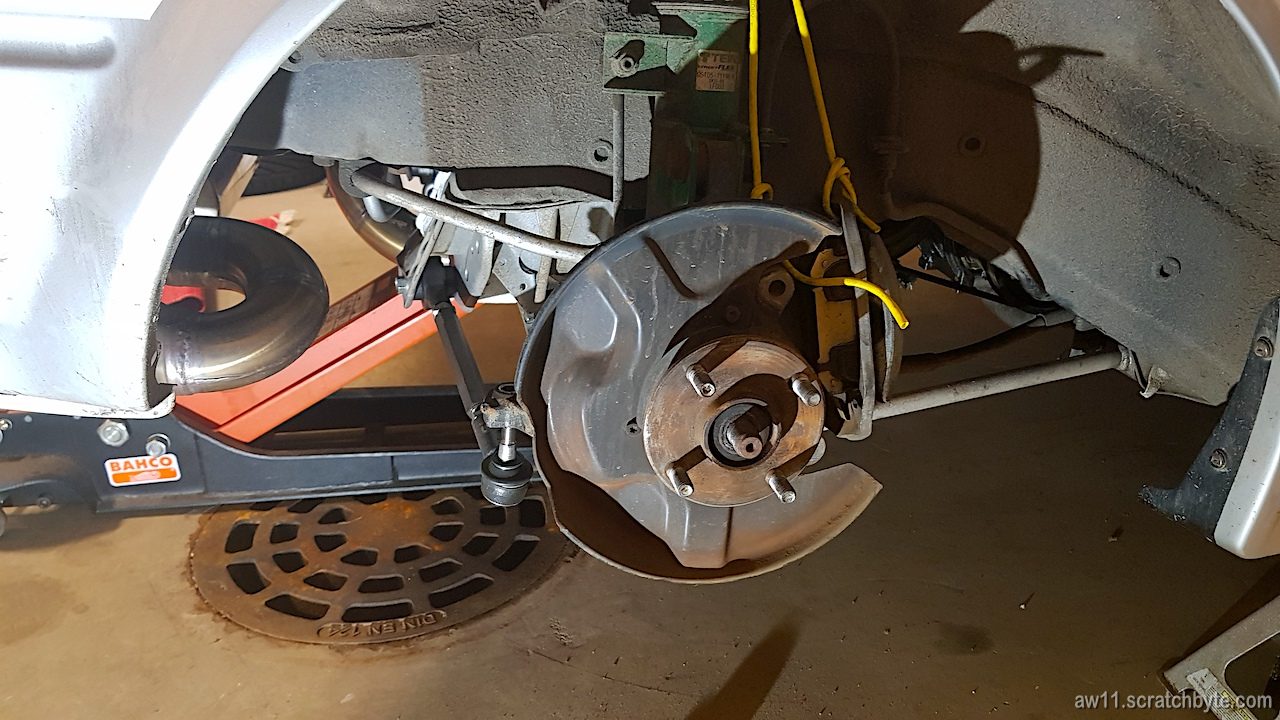
I deliberately left the brake shields out and decided to mod them so I could remove them without taking the whole bearing assembly apart.
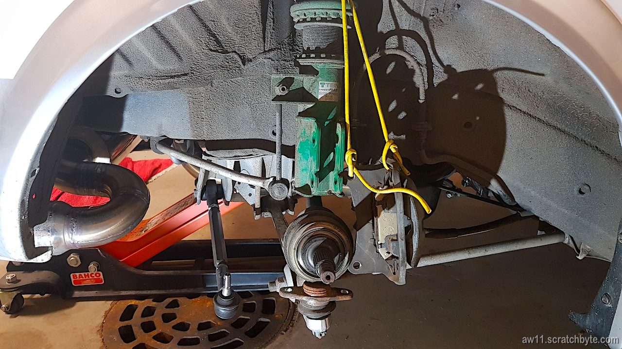
The yellow wire that holds the brake caliper is one of those net cables that come with routers. The surface material is weird, it sticks to itself and holds very well when tied badly.
The line I cut the shields, just visible on the right side of the hub centerline.
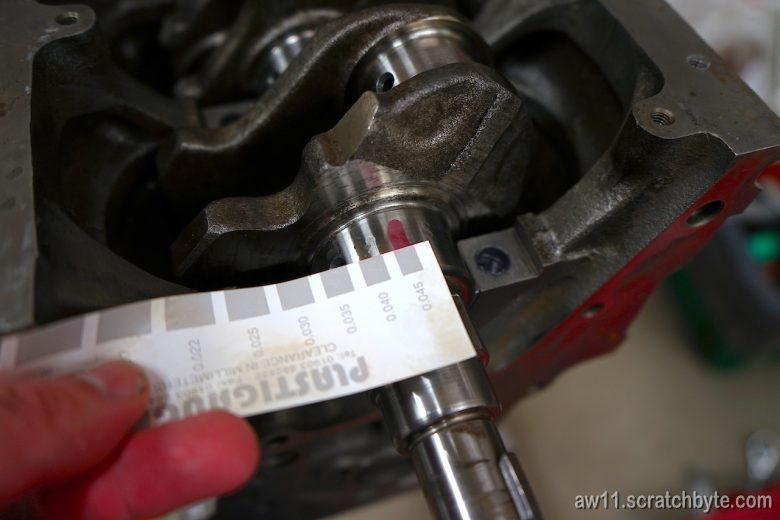
Checking the clearances with plastigauge (not plastigage). I had PL-X, which is for clearances between 0.018 – 0.045mm.
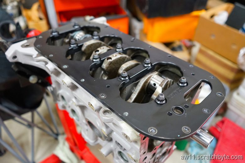
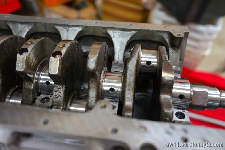
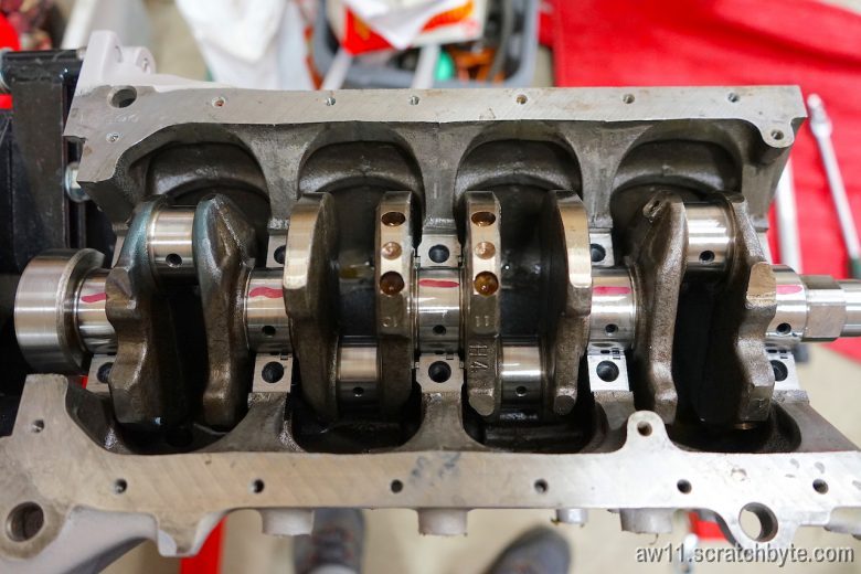
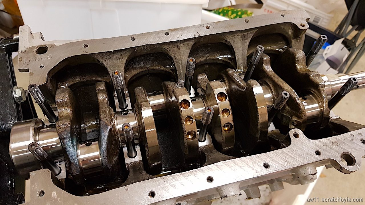
Below: ready to go. Everything still torqued down.
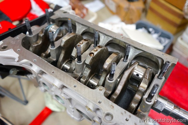
Below: nuts and girdle off, studs loosened
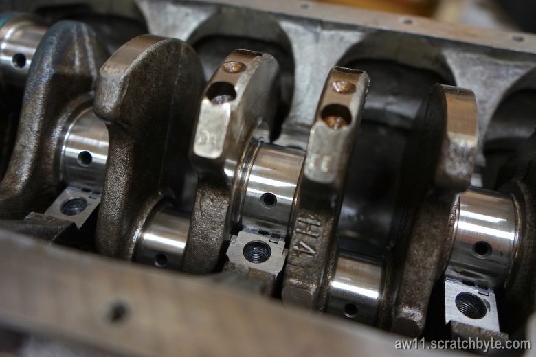
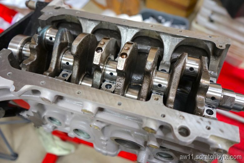
Main caps are off. Crank still looks shiny and smooth. Wiped excess oil off before inserting plastigauge.
Applying plastigauge
After main caps, studs, girdle, nuts and everything, quick two step tightening to 80Nm and then removing everything again. Plastigauge is showing very constant clearances.
Clearances are constant between every main cap + they are constant across the bearing surface, showing no deformations.
One of the narrowest strips showing 0.045mm clearance. Rest of the strips were around 0.040mm, which is within the allowed range.
Toyota manual states the standard clearance should be between 0.015 to 0.033mm, except if replacing the cylinder block, when the standard clearance is between 0.015 and 0.045mm. I guess the line boring is close to replacing the block.
Leftmost conrod neck (cylinder 4) is showing some colorization from the crank polishing.
Just wondering if bearings grow a little and close the clearance while engine is running…?
Few thoughts:
I havent visited the garage for a while and the temperature was low (around +10°C) when I measured everything. According to plastigauge, cold is not a problem when in storage, only high temps.
What is the shelf life of plastigauge? It didnt feel brittle or otherwise damaged so I thought it was good. How does this affect the measuring?
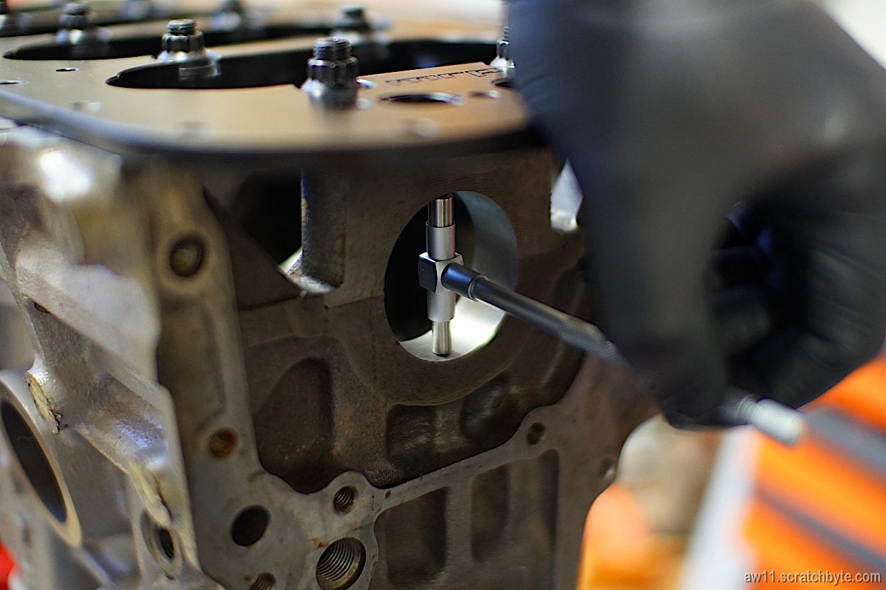
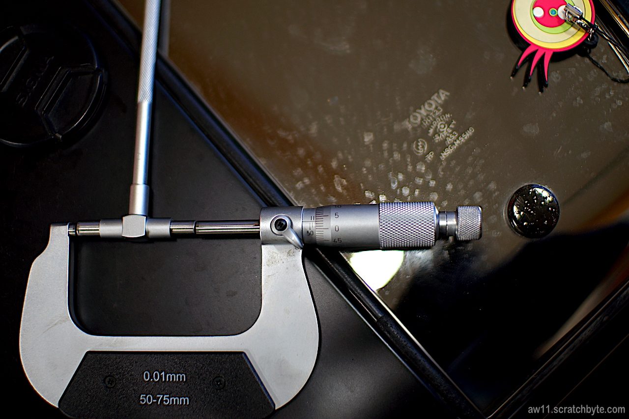
What is the measurement error here? With micrometres I get the following numbers:
Honed crank bore inner diameter 52.03mm
Bearings thickness 2.000mm – 2.005mm
Crank diameter 47.995mm
Crank bore ID – 2x bearing thi = 48,02mm – Crank dia = 0.035mm
Using micrometers I’m getting a little bit tighter clearances, so I have to cast some doubts towards plastigauge. Calculating clearances gives results between 0.025mm to 0.035mm while maximum being 0.040mm. Plastigauge varies between 0.040mm and 0.045mm.
Edit: I just realized that most of the measures taken with micrometers were done in temperatures between +20°C and +25°C. Measures with plastigauge were done in temperatures around +8°C to +11°C. This could be something called thermal expansion. I think everything is ok 🙂
Ok, admittably, it is bit irrelevant to be upset about the fuel line at this point. Still, I got some fails and some wins today.
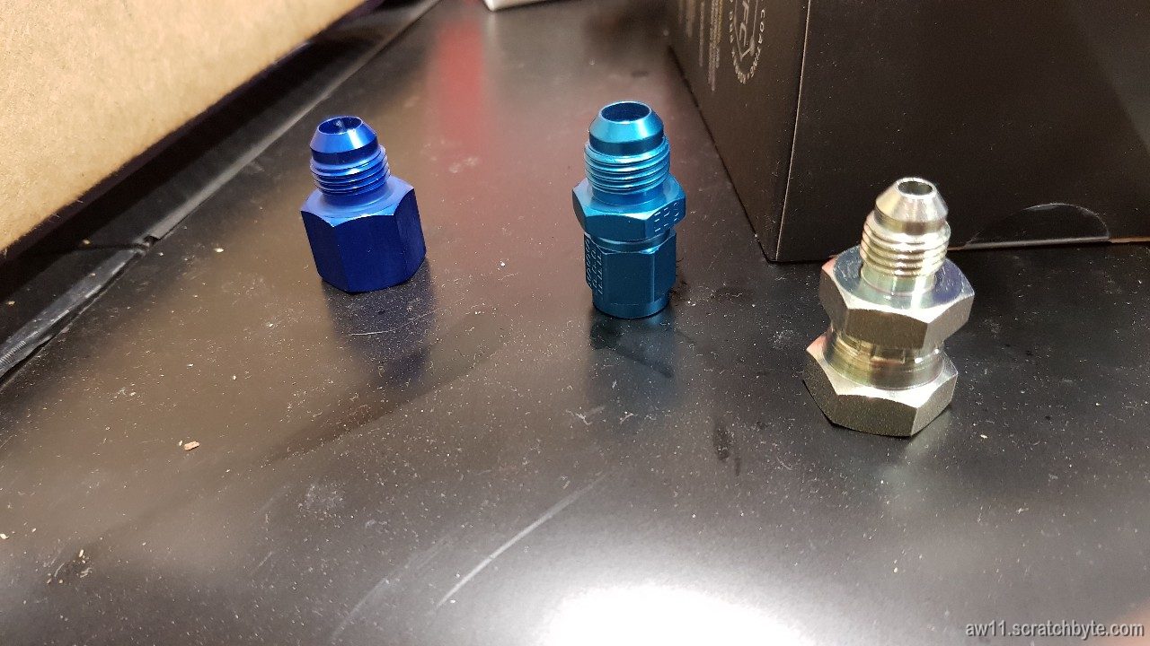
The adapters that I got – from left to right:
Indigo blue aluminum 1/4″ BSP to AN6 adapter – the first fail. It is exactly as it should be but the cone where the flare should seal itself is not convex, it is concave.
The other kind of blue aluminium adapter is size adapter, from AN4 to AN6. It is actually perfectly fine but the fail lies in the bore diameter. It is less than 5mm.
Yellow zinc steel adapter, from 1/4″ BSP to AN4. Also fail. The bore is 4.5mm which is unacceptable, I wont go below 5mm in any situation. It should mate with the previous AN4-AN6 -adapter,but the combined 4.5mm bore diameter just sucks. The steel BSP adapter looks like it could be bored, but that feels bit shady.
The only win for today is that my thread identification might be wrong. The original hardline to fuel filter bit doesnt have a 1/4″ BSPP thread, it is something called Japan Industry Standard (JIS) thread. It just happens to be exactly like BSPP but there is some fiddling with the sealing cone.
Good thing that japanese didnt try to reinvent the whole wheel. They have a JIS screwdriver that looks very much like PH2 screwdriver but it is incompatible and if used with wrong tool, it will fuck up the screw. Now, there is also this JIS pipe/hose/whatever thread. Exactly like BSPP but the sealing cone is different or reversed. Wont seal if JIS is mated to BSPP. Unbeliveable stuff but still ah so fantastic figuring this shit out 😀
I found some sealing adapters online that could work. They’re cone adapters that come between pipe flare and concave BSPP bit.
Ok, the fuel line still bothers me. The replacement I recently got wasnt totally satisfactory, as I noticed the R-thread adapter cone on the replacement had a hole with smaller diameter.
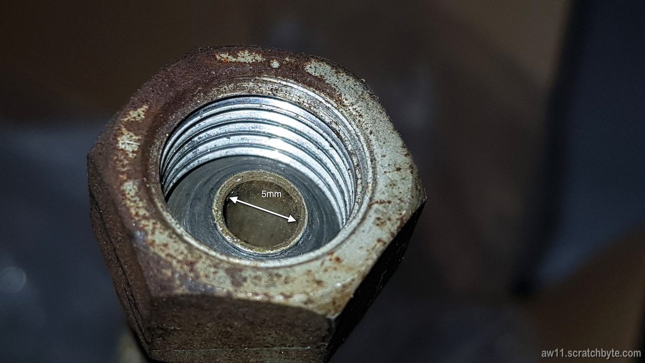
Below, I have a picture of the stock one. This is not from my MR2, instead I bought a used one to examine it and get it right.
To make clear what bit I have here, this is the rubber line that comes between the fuel tank hard line and the fuel filter.
Fuel filter end has a banjo with 5mm diameter hole. Banjo and the bolt itself are 12mm (M12 x 1.25 to be exact)
This end of the line seems to have a shallow cone or a ball head, I just cant make it out which one it is, but it is supposed to seal against the fuel tank hard line that has a similarly sized flare and a flare nut behind it.
The threads don’t seal the connection, but the nuts should be tightened well to make sure the flare is well pressed against the cone to make the actual seal.
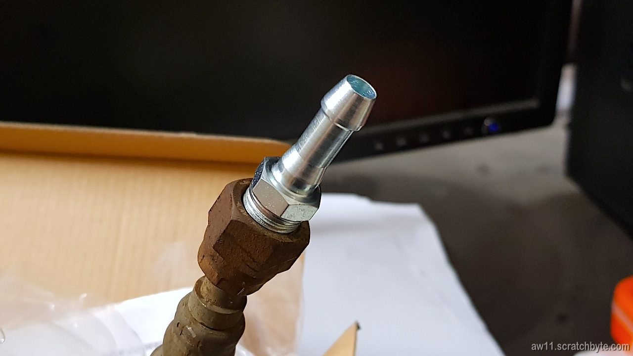
This very phallic looking thing is a cheap hose barb which has the exact same thread as the fuel line. I can now confirm, that the thread on the fuel line is 1/4″ R-thread, also known as British Standard Pipe Parallel (BSPP) and it has a 19 threads per inch (TPI) – 1/4″ -19 BSP(P)
It is exceptionally hard to find an adapter for it that has bigger diameter hole to fuel to pass through! Even harder if you want to have something like AN/JIC -terminal on the other side 😀
Last time in the inspection I barely passed because the rear bearings were not doing that well.
So – what else – I waited to the last possible moment to do them 😀
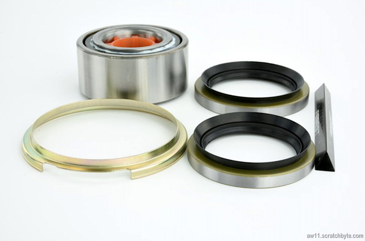
I used two Febest DAC387433-36KITs, which should be compatible with the Toyota 90369-38019 and 90369-38003 bearings and 04422-32010 seal kit.
The seal kit looks bit weird. Dust deflector (43246-32011 equiv.) has a unusual notch in it and I dont know which way I should position it. You can see the notch in the picture below which I loaned from Febest catalog.
Edit: the notch is for speed sensor – I’ll try to figure out if i need to cover it.
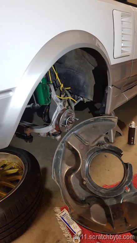
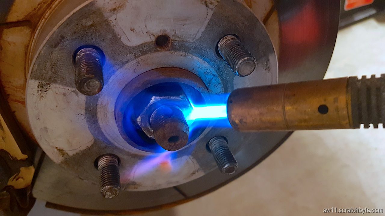
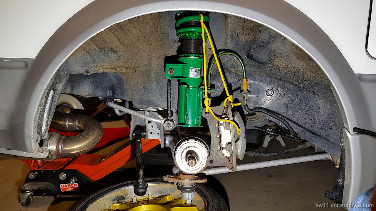
Below: Already going somewhere here. Caliper hanging, balljoints loose and disc is gone.
Little bit heat and penetrating oil helped a lot. Drive shaft nuts werent that stuck, just made sure they were coming off easily.
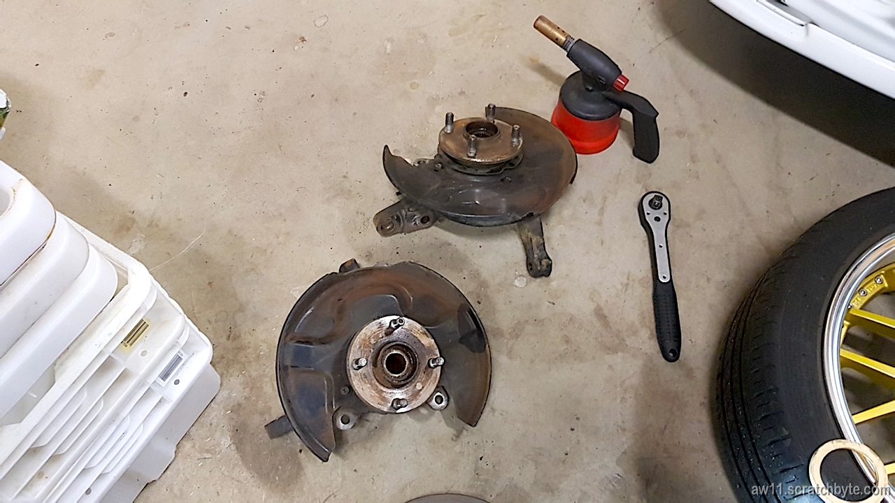
Driver side is done.
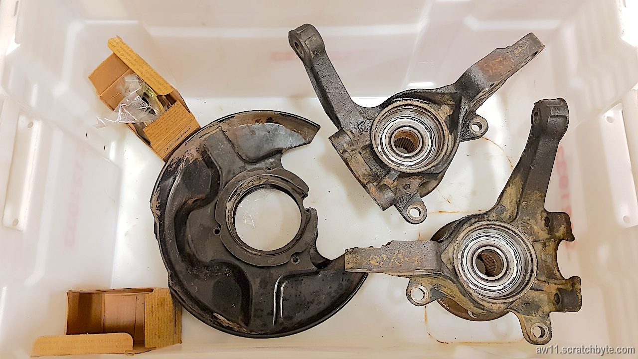
Both sides ready to get their bearings replaced
Following two pictures are from Mr. Reynolds family album:
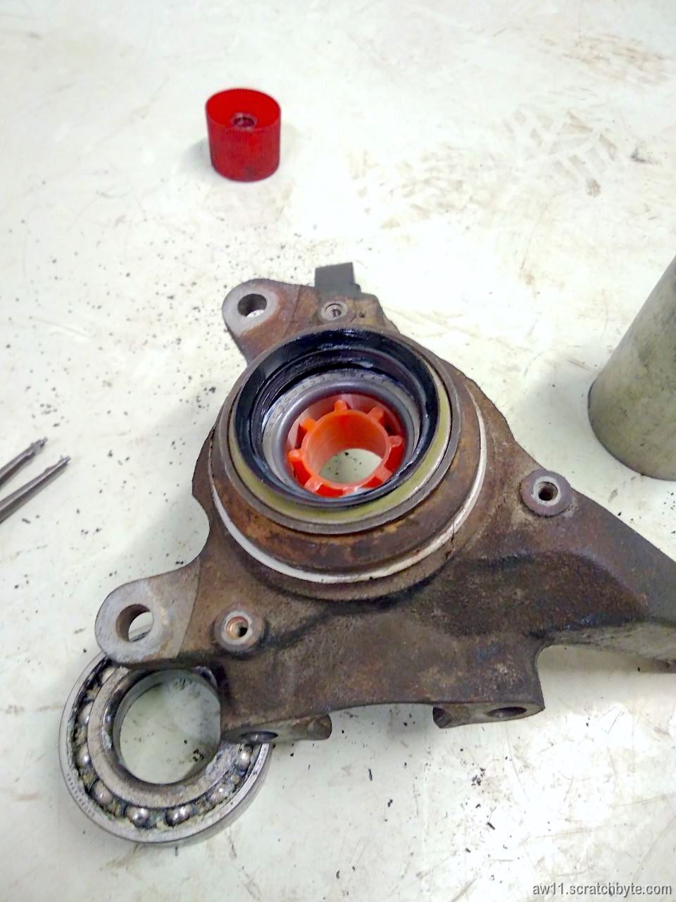
Below: Orange plastic support inside the new bearing.
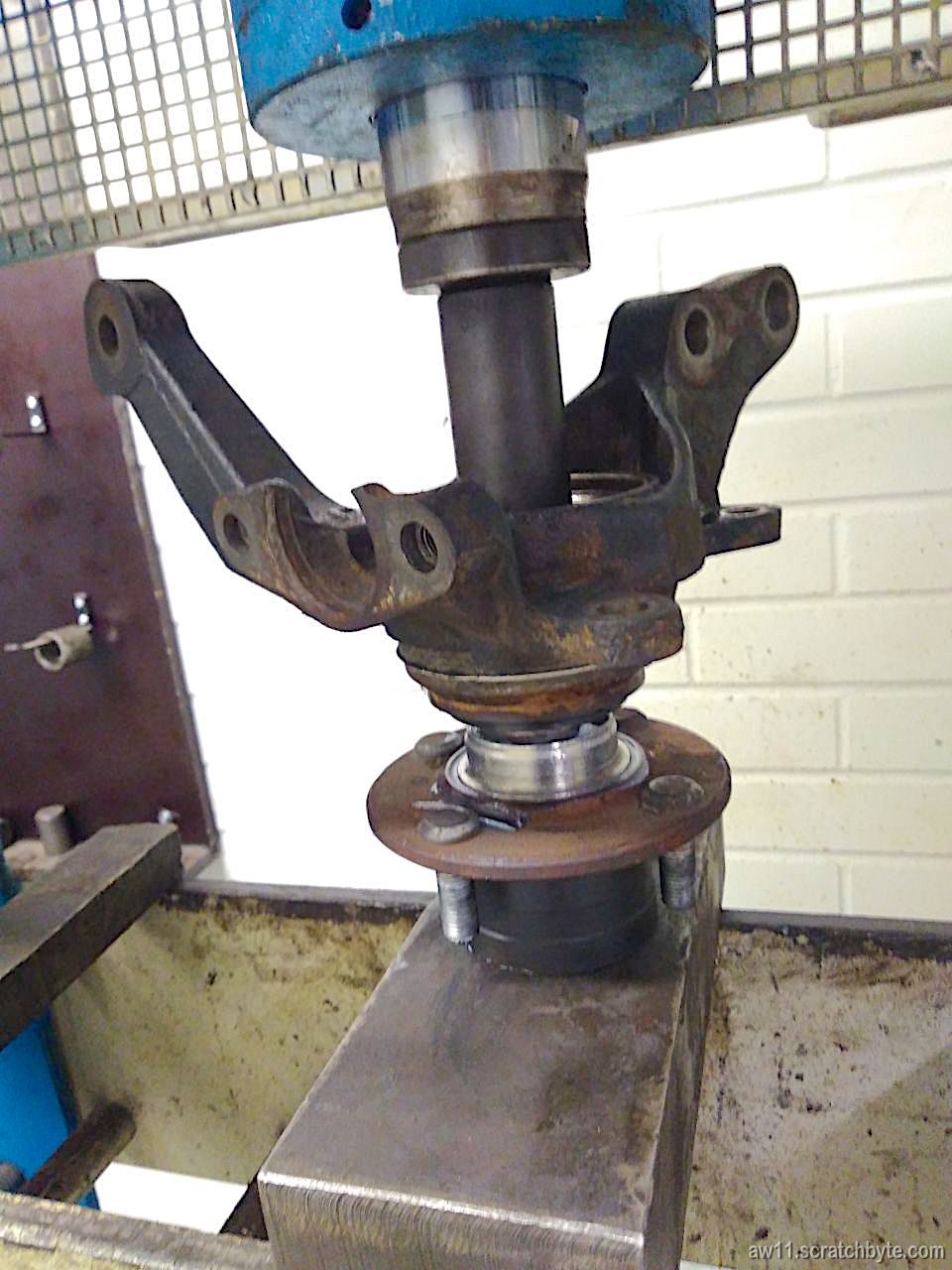
Below: Some hydraulics were used and the old bearings removed.
Meanwhile, I was cleaning the rest of the suspension:
Below: The knuckles with new bearings. Both of them have something written on them but I cant make out what. The clearer one looks like 12713.35 or /21/3.35…
Guessing it could be markings from previous bearing change, I looked from wikipedia how japanese write the dates in imperial calendar format.
Format is yy/mm/dd, but the numbers here dont make sense that way. The last two digits after the dot could be kilometers like 35万km (meaning 35000km)
Anyhow, I’m going to modify the brake shields so they can be removed without taking the whole bearing assembly off.
While googling, found out following bearings should have the same size. Doublecheck and dont trust me.
I got some comments recently from bot, who suspected that the middle main cap deforming while ARP nuts were tightened could be the reason behind my seized crank.
The possibility of twisted or tweaked middle main cap didnt cross my mind. I had already gotten my block back from machine shop, when bot commented this thing, but I didnt have spare time to actually look my block until now.
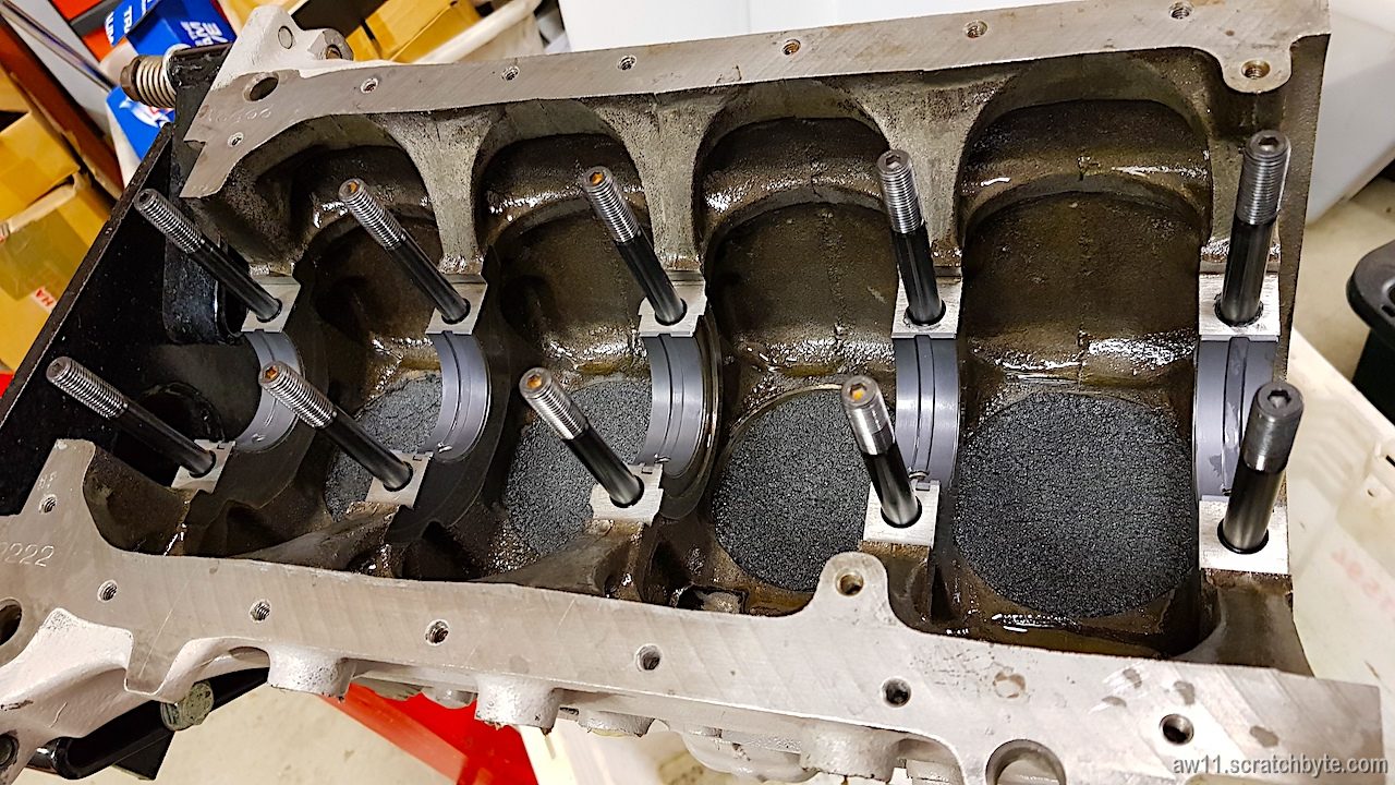
I spent two hours carefully taking everything apart and examining the parts (once again). Block still had some cutting oil + metal particle residue from the honing and it probably was also mixed with that ARP moly stuff that was used on the threads. It took some time to get everything clean.
Below: I made a set of cylinder plugs from foam plastic to help with cleaning and installing parts.
Putting everything back together went well. Bearings and ARP studs went in smoothly and so did the crank (after cleaning it millionth time). When I got to the thrust bearings I eyeballed them with suspicion but they didnt reveal anything to me. Lower ones slid in easily and the upper ones went in with the main cap.
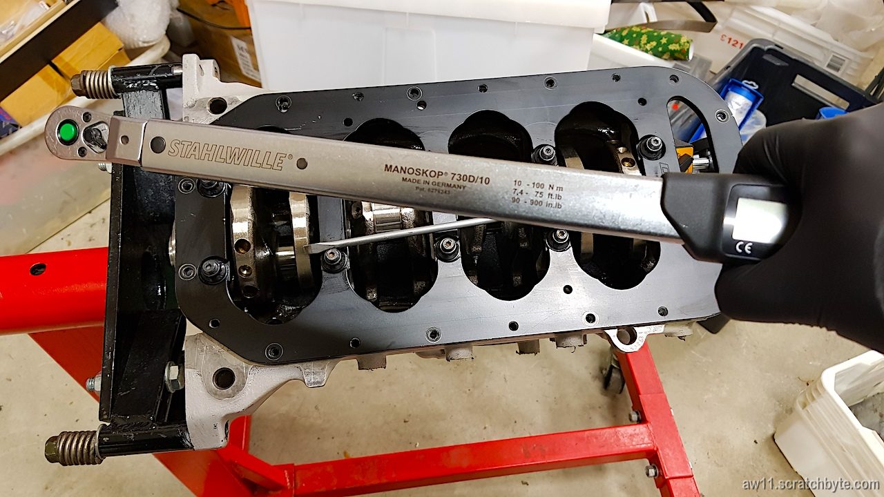
Last bits were the MRP girdle and ARP washers and nuts. I tightened the nuts in four steps starting from 20Nm and ending to 80Nm, stopping in between to rotate the crank and see if there were any problems. The crank rotated freely every time.
Below is my torque wrench. I bought this one just for this project to get the critical parts correctly torqued.
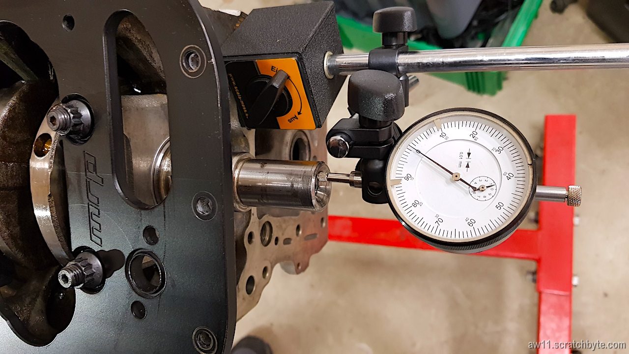
It started to seem that the honing did help and the middle cap wasnt causing any trouble. I grabbed the crank from the both ends and tried to shake it, but it felt like there wasnt any play. I went to get Widrics almost unused dial indicator and set it up.
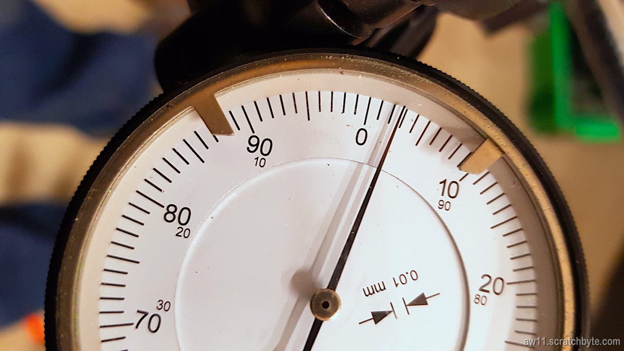
Below: zeroed
Then I poked the crank with screwdriver like the Toyota manual says.
Result: seems that my crankshaft end play is 0.03mm. Toyota manual says that the minimum acceptable is 0.02mm 😀
Some thoughts:
I’ve introduced plenty of new parts to my engine block. I have new main bearings and new thrust bearings, both with extra moly coating on them. Also, a set of longer ARP studs (with washers and nuts) for the girdle and the girdle itself.
Every new part creates a huge number of unknowns and it is absolutely important to check that everything is where they should be. Mr. Manon probably disagrees with me, but even the girdle could have been the source for my problems, although it got complemented by the machinist doing the honing 😀
Just by fitting all the parts together I found out that the middle main cap was not the problem. I’m not entirely happy of this method, but it has to do now. I dont have the resources and possibilities of McLaren to build engines 😀
Edit: My preferred method for the problem would have been different. I prefer to measure things until I have numbers, results and hard evidence. Except putting things back together was more practical and efficient method… 😀
I didnt measure the bearings yet, so next time I’ll be messing with plastigage.